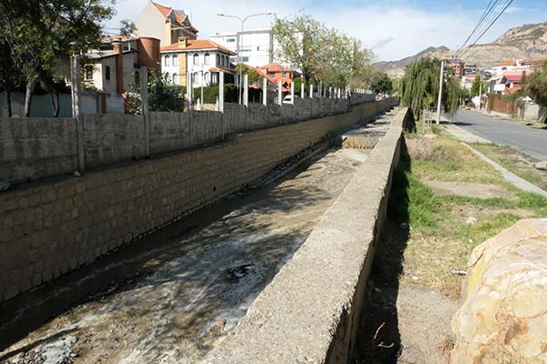
1. INTRODUCCIÓN
El desarrollo de ondas de rollo (u ondas pulsantes) en el flujo de un canal abierto continúa atrayendo
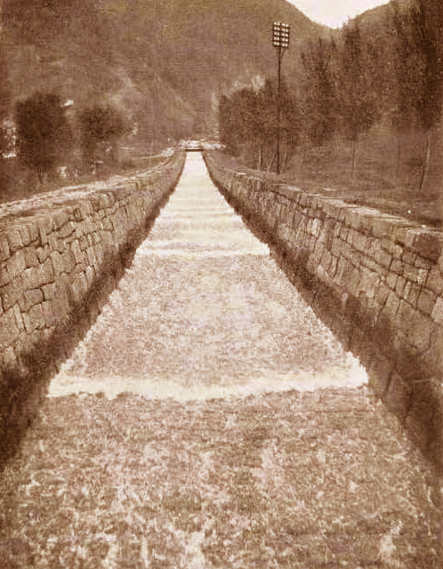
el interés tanto de investigadores como de ingenieros profesionales. En 1907, Cornish mostró
por primera vez una fotografía de este fascinante fenómeno en un artículo publicado
en el Journal of the Royal Geographical Society (Fig. 1)
(
Una onda de rollo es un fenómeno inusual y a menudo fascinante, a ser admirado por aquéllos que tienen la suerte de observarlo. Sin embargo, en ciertas circunstancias, puede resultar inquietante e inclusive peligroso. Por lo tanto, es imperativo que los ingenieros hidráulicos conozcan los principios que rigen la formación y propagación de las ondas de rollo, de modo que el diseño pueda tender a minimizar los posibles impactos negativos.
En este artículo enfocamos el estudio de caso de algunos tributarios del río La Paz, en La Paz, Bolivia,
en el cual se ha documentado la recurrencia de ondas de rollo con una frecuencia
preocupante. Localmente, estas ondas de rollo,
a menudo de gran tamaño, se denominan ondas pulsantes. La Paz, una ciudad de
aproximadamente 800.000 habitantes y sede del Estado Plurinacional de Bolivia, presenta
un entorno geomorfológico peculiar: Está construida casi en su totalidad
dentro de una inmensa cárcava, con varios arroyos de pendiente muy
pronunciada que drenan su extremo
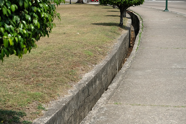
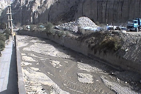
En los últimos 30 años, el desarrollo urbano intensivo ha traído como consecuencia la canalización
de varios de los principales arroyos tributarios con canales revestidos de mampostería,
destinados a transportar las aguas de avenida de la manera más eficiente.
Sin embargo, tal como se construyeron, los canales de drenaje han modificado
la sección transversal de los arroyos de modo que los eventos de olas de rollo
ahora son recurrentes (2019 a 2024), en lugares donde no existían antes de la canalización.
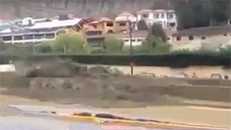
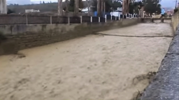
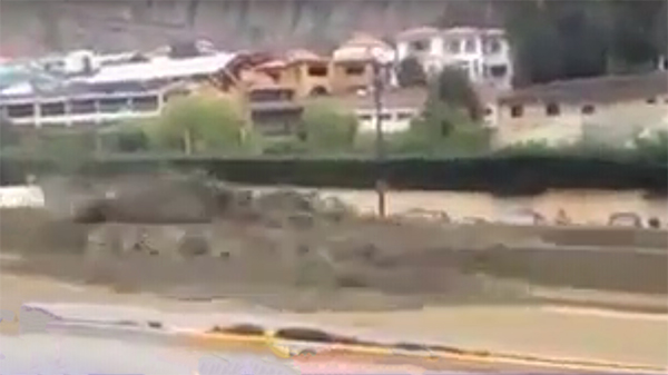
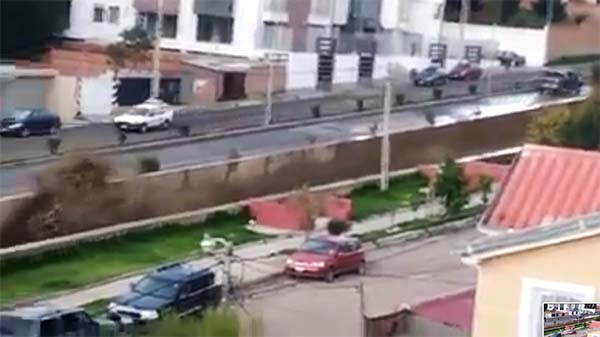
A modo de ilustración, aqui mostramos dos videos tomados en La Paz en los últimos años.
El primero muestra un evento de onda de rollo en el río Achumani,
afluente del río La Paz (Fig. 4).
En el segundo video se observa una onda de rollo en el río Huayñajahuira,
otro afluente del
En este artículo se revisan los antecedentes históricos y se examina la teoría, experiencia y posibles soluciones para controlar, atenuar y/o manejar las ondas de rollo de manera que la sociedad tenga la seguridad de que en el futuro no vayan a causar daños personales y/o materiales. 2. PERSPECTIVA HISTÓRICA En 1945, V. V. Vedernikov presentó, en idioma ruso, un análisis matemático exhaustivo de las ondas de rollo (Vedernikov, 1945; 1946). Casi al mismo tiempo Craya publicó un artículo sobre la inestabilidad del flujo en la revista francesa La Houille Blanche (Craya, 1945). Sin embargo, el trabajo definitivo de Craya sobre el tema de la inestabilidad del flujo se publicó sólo siete años después (Craya, 1952). En un artículo publicado en Transactions of the American Geophysical Union, Ralph W. Powell bautizó el criterio de Vedernikov como el número de Vedernikov (Powell, 1948). Más adelante, Ven Te Chow confirmó la existencia del fenómeno en su reconocido libro de texto (Chow, 1959). Craya aclaró el criterio de Vedernikov interpretándolo como el umbral en el que la celeridad de la onda cinemática es igual a la de la onda dinámica. Ya en 1900, Seddon, trabajando en el Río Bajo Misisipi, había derivado la expresión para la celeridad de la onda cinemática, es decir, una onda gobernada únicamente por la fricción y la gravedad (Seddon, 1900). Más tarde, Lighthill y Whitham (1955) delinearon los fundamentos teóricos de la onda cinemática, destacando su aplicación a la propagación de ondas de inundación. A diferencia de una onda cinemática, la onda dinámica de la mecánica de fluidos clásica, la cual se propaga con la celeridad de Lagrange, es una onda gobernada únicamente por la inercia y el gradiente de presiones (Lagrange, 1788). Se observa que la celeridad relativa de la onda dinámica (de Lagrange) es el denominador del reconocido número de Froude (Ponce, 2014: Capítulo 1). Ponce (1991) ha presentado un tratamiento teórico unificado de los números de Froude y Vedernikov, demostrando que son esencialmente independientes. El análisis siguió el trabajo seminal previo de Ponce y Simons (1977), el cual sentó las bases para el tratamiento del flujo inestable en canal abierto a lo largo del espectro adimensional de números de onda. Ponce confirmó el hallazgo anterior de Craya con respecto al umbral de inestabilidad del flujo, es decir, cuando las ondas de masa de Seddon (es decir, las ondas cinemáticas) superan las ondas de energía de Lagrange (las ondas dinámicas). Este umbral se produce cuando la celeridad de la onda cinemática es igual o superior a la celeridad de la onda dinámica, es decir, cuando el número de Vedernikov V ≥ 1. Por lo tanto, la naturaleza de las ondas de rollo está intrínsecamente ligada al concepto del número de Vedernikov. 3. EL NÚMERO DE VEDERNIKOV
Ponce (1991) y más recientemente, Ponce (2014) han identificado tres velocidades de interés en el flujo en canal abierto:
Se definen las siguientes variables:
Por lo tanto, solamente hay tres velocidades características en el presente
análisis:
Se observa claramente que los números de Froude y Vedernikov son independentes;
Así, la curva de gasto caudal-area puede expresarse en términos de los números de Froude y Vedernikov como sigue:
En resumen, el número de Froude es la relación entre la velocidad del flujo y la celeridad relativa de la onda dinámica. Para F < 1, prevalecen condiciones de flujo subcrítico y las perturbaciones superficiales pueden trasladarse aguas arriba, lo que hace posible el control aguas abajo. Para F > 1, prevalecen condiciones de flujo supercrítico y las perturbaciones superficiales no pueden trasladarse aguas arriba; por lo tanto, el flujo podría controlarse sólo desde aguas arriba. El criterio de Froude es estrictamente aplicable al flujo uniforme, aunque en la práctica su uso se ha extendido a otras condiciones de flujo. El número de Vedernikov es la relación entre la celeridad relativa de la onda cinemática y la celeridad relativa de la onda dinámica. Por lo tanto, el criterio de Vedernikov es estrictamente aplicable al flujo no permanente. Para V < 1, las ondas dinámicas viajan más rápido que las ondas cinemáticas y, en consecuencia, el flujo es estable, es decir, libre de ondas de rollo. Por el contrario, para V > 1, las ondas cinemáticas viajan más rápido que las ondas dinámicas y, en consecuencia, el flujo es inestable, es decir, propicio al desarrollo de ondas de rollo. Sin embargo, el que las ondas de rollo ocurran o no dependerá de la condición en el contorno (véase la Sección 5). Por lo tanto, se considera que el criterio de Vedernikov es necesario, pero no suficiente, para la aparición de ondas de rollo. Los roles de la masa y la energía son fundamentales para el análisis de las ondas de rollo. Está bien establecido que, mientras que las ondas cinemáticas transportan masa, las ondas dinámicas transportan energía (Lighthill y Whitham, 1955). Por lo tanto, se observa que la aparición de ondas de rollo ocurre cuando el transporte no permanente de masa supera al transporte no permanente de energía. En este sentido, las ondas de rollo son una manifestación física de la preponderancia del transporte de masa sobre el transporte de energía en el flujo no permanente en canales abiertos. 4. EFECTO DE LA SECCIÓN TRANSVERSAL El número de Vedernikov es:
Si bien los ingenieros hidráulicos están muy familiarizados con el número de Froude, no se puede decir lo mismo del número de Vedernikov, que continúa siendo dejado de lado en la práctica de la ingeniería hidráulica (Ponce, 2002). Para centrarnos en el número de Froude, más conocido, el número de Vedernikov se puede expresar de la siguiente manera:
La Ecuación 4 muestra que el número de Vedernikov y la inestabilidad del flujo relacionada están determinados por el producto de (β - 1) por el número de Froude F. En la práctica, el número de Froude no varía en un amplio rango; por lo tanto, (β - 1) es el factor determinante en la inestabilidad del flujo.
Según la teoría, la estabilidad neutra, es decir, el umbral de inestabilidad de flujo, corresponde a V = 1. De la Ecuación 4, el número de Froude para la estabilidad neutra es:
Para desentrañar el significado físico de la inestabilidad del flujo, es necesario examinar la verdadera naturaleza de β, el exponente de la curva de gasto caudal-área (Q - A). Básicamente, β es la relación entre la celeridad de la onda cinemática ck y la velocidad media del flujo u. En otras palabras, β es el factor por el cual se multiplica la velocidad media del flujo para obtener la celeridad de la onda cinemática. Para β ≡ 1, la celeridad de la onda cinemática es igual a la velocidad media del flujo, lo que arresta (impide) la inestabilidad del flujo.
El valor de β es una función del tipo de fricción de fondo
y de la forma de la sección transversal.
El flujo turbulento puede expresarse en términos de las ecuaciones de Manning o de Chezy.
La forma de la sección transversal puede variar ampliamente y, con ella, el valor de β.
Existen tres formas asintóticas de sección transversal, en términos de los valores aplicables de β
La Tabla 1 muestra los valores de β correspondientes a combinaciones seleccionadas de fricción de fondo y forma de la sección transversal. Siguiendo la Ec. 5, los valores del número de Froude neutralmente estable Fns se muestran en la última columna. El rango práctico de valores de β mostrados es: 1 ≤ β ≤ 3, en el cual el valor más alto (β = 3) corresponde al flujo laminar (hidráulicamente ancho) (es decir, flujo superficial en un plano) y el valor más bajo (β = 1) a la forma de la sección transversal inherentemente estable. Se atribuye a Liggett (1975) el mérito de haber sido pionero en la teoría del canal estable.
El valor central del rango factible de β, correspondiente al flujo turbulento en un canal hidráulicamente ancho es β = 5/3 para la fricción de Manning y β = 3/2 para la fricción de Chezy. Los valores correspondientes de la celeridad de onda cinemática relativa adimensional (β - 1) son 2/3 para Manning y 1/2 para Chezy. Por lo tanto, bajo la fricción de Manning en un canal hidráulicamente ancho, una onda cinemática viaja aguas abajo con una velocidad que es aproximadamente 2/3 más rápida que la velocidad media del flujo; de la misma manera, bajo la fricción de Chezy, es 1/2 más rápida.
El valor de β = 1, correspondiente al canal inherentemente estable,
merece mayor elaboración.
Como alternativa, tiene algún sentido diseñar un canal para un valor finito de Fns , cuidadosamente elegido como un valor físicamente realista que el flujo no tenga probabilidades de superar (Ponce y Díaz, 2016). Para un canal condicionalmente estable, el valor aplicable de β puede calcularse mediante la Ec. 6.
Por ejemplo, para Fns = 25, la Ec. 6 resulta en β = 1,04. Por lo tanto, los valores de β superiores a 1 pero cercanos a él son suficientes para asegurar la estabilidad dentro de un rango práctico de números de Froude de estabilidad neutra (2,5 ≤ Fns ≤ 25). La Tabla 2 muestra los valores de β adecuados para el diseño. Por ejemplo, para una sección transversal con β = 1,2, el flujo se volverá inestable a medida que el número de Froude supere a 5.
En resumen, se demuestra que β, el exponente de la curva de gasto descarga-área (Ec. 2) y una característica de la sección transversal, es en gran medida responsable de la aparición de ondas de rollo en flujo inestable (no permanente) en un canal abierto. Sin embargo, un análisis más detallado muestra que la condición β puede ser necesaria pero no suficiente. Como lo demostraron Ponce y Simons (1977), en flujo turbulento en canal abierto, a lo largo del espectro de números de onda adimensionales, es probable que ciertos valores de estos últimos amplifiquen las ondas más que otros. Esta proposición se presenta con más detalle en la siguiente sección.
5. PROPAGACIÓN DE ONDAS EN CANALES
La condición necesaria y suficiente para la formación de ondas de rollo puede analizarse utilizando
la teoría de propagación de ondas poco profundas de Ponce y Simons (1977). Estos autores aplicaron
el método de estabilidad lineal al conjunto de ecuaciones que gobiernan el flujo no permanente
en canales abiertos, comúnmente conocidas como ecuaciones de San Venant. El análisis
condujo a funciones de celeridad y atenuación de varios tipos de ondas en aguas poco profundas,
incluidas las cinemáticas, de difusión, cinemáticas-difusión mixtas y dinámicas
(Ponce, 2014: Capítulo 10).
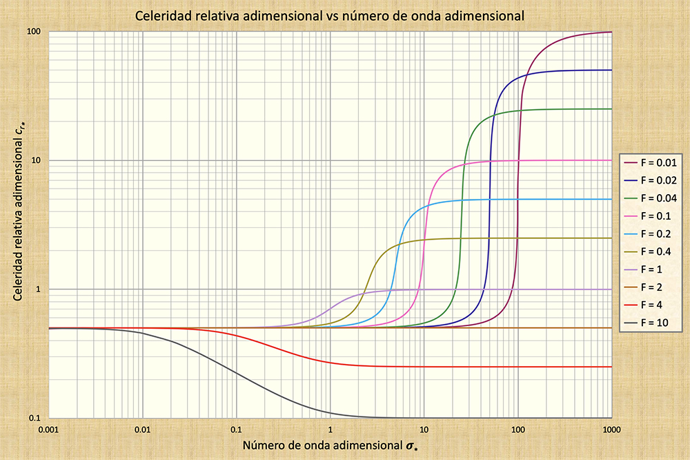
La Figura 6 muestra valores de celeridad de onda relativa adimensional
cr* (ordenadas)
en un amplio rango de números de onda adimensionales
σ* (abscisas). Esta figura muestra
que cr* ⇒ 0.5 cuando
La Figura 6 también muestra que para F = 2, cr* es constante e igual a 0,5, lo cual corresponde al valor del número de Froude neutralmente estable (V = 1) para un canal hidráulicamente ancho con fricción de Chezy (Tabla 1). Por lo tanto, para F = 2, todas los tamaños de onda viajan con la misma celeridad, lo que confirma ampliamente la validez de la teoría de Vedernikov. La atenuación o amplificación de las ondas se produce cuando el valor de cr* varía a lo largo del espectro de números de onda adimensionales. Se puede demostrar que ni las ondas de Seddon (cinemáticas) ni las ondas de Lagrange (dinámicas) están sujetas a (ninguna cantidad de) atenuación o amplificación. La Figura 6 describe la atenuación de onda para F < 2 (es decir, para un gradiente cr* positivo) y la amplificación de onda para F > 2 (para un gradiente cr* negativo), lo que confirma la teoría de Vedernikov.
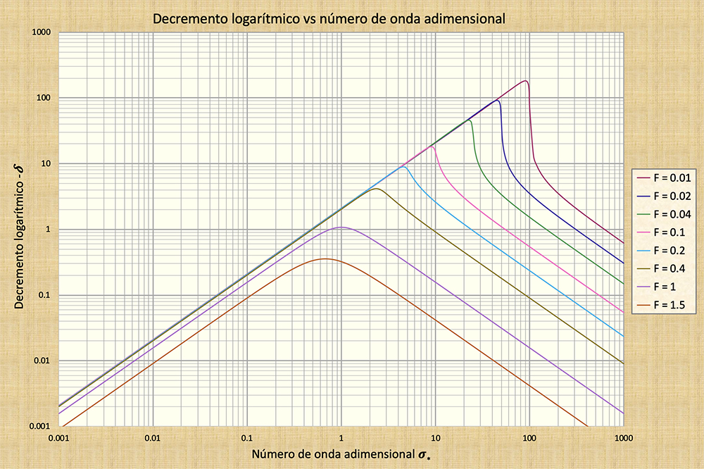
La Figura 7 muestra los valores del decremento logarítmico δ (en las ordenadas) a lo largo de un amplio
rango de números de onda adimensionales σ*
(abscisas), para números de Froude en el
rango 0,01 ≤ F ≤ 1,5. [El valor F = 2 tiene atenuación cero; por lo tanto, no se pudo
representar gráficamente en la escala logarítmica]. En correspondencia directa con la
Fig. 6, en la Fig. 7 se muestra que la atenuación de onda es más marcada a medida
que el número de Froude disminuye a F = 0,01.
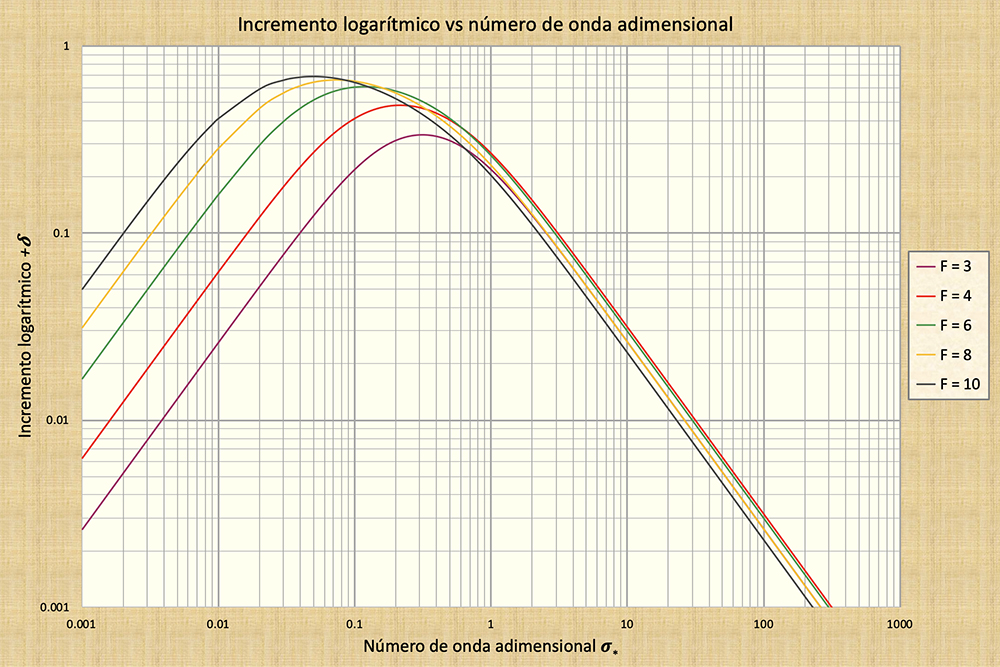
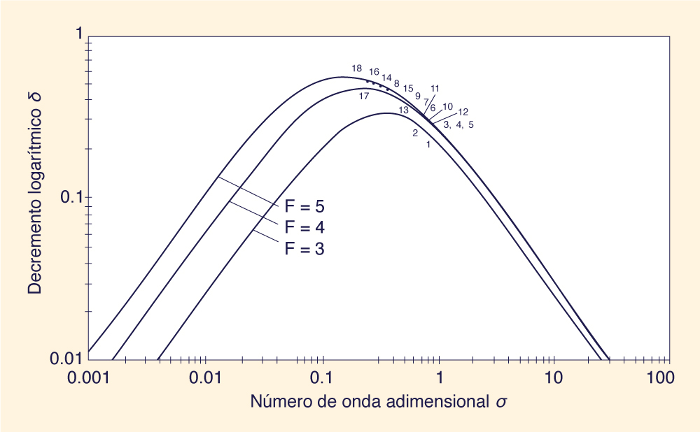
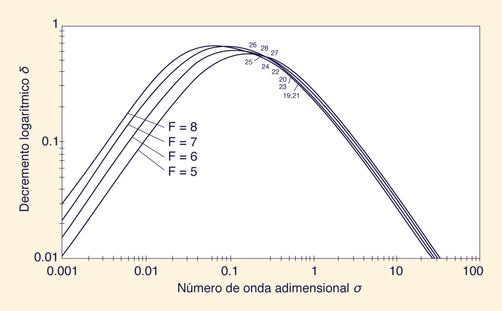
La Figura 8 muestra valores de incremento logarítmico +δ (ordenadas) (es decir,
amplificación de onda) a través de un amplio rango de números de onda
adimensionales σ* (abscisas),
para números de Froude en el rango
El análisis anterior confirma que la amplificación de las ondas se producirá para
números de Froude La experiencia práctica sugiere que el criterio de Vedernikov (V ≥ 1) es necesario pero no suficiente para la aparición de ondas de rollo. Las ondas de rollo no ocurren todo el tiempo en canales empinados en cuanto se cumpla el criterio de inestabilidad. De hecho, se observa que las ondas de rollo son una ocurrencia inusual. En resumen, la teoría de propagación de ondas poco profundas de Ponce y Simons (1977) confirma la teoría de Vedernikov. Lo más significativo es que, para los números de Froude en el régimen inestable, el valor del incremento logarítmico δ (consultar la Figura 8) no es constante, y alcanza su pico en el punto de inflexión de la función adimensional de celeridad relativa vs. número de onda (consultar la Fig. 6). Este hecho establece claramente un rango preferencial de números de onda adimensionales para la amplificación de perturbaciones de flujo en canal abierto y el consecuente desarrollo de las ondas de rollo. 6. VERIFICACIÓN EXPERIMENTAL
La Figura 8 muestra el rango de números de onda adimensionales para el cual es probable que
la amplificación de onda sea más fuerte. De hecho, hay un valor de
σ* para el cual
el incremento logarítmico +δ es máximo.
La Figura 8 muestra que para F = 4 (la curva roja), +δpeak
= 0,5 corresponde a
En la Fig. 6,
la amplificación de la onda está asegurada por la naturaleza de la variación
de la celeridad de onda relativa adimensional para Para verificar la teoría, Ponce y Maisner (1993) utilizaron los datos medidos y publicados por Brock, desarrollados en el Instituto Tecnológico de California. Brock (1967) midió las profundidades de cresta y los períodos de las olas en una amplia gama de condiciones de flujo. Ponce y Maisner compararon los números de onda adimensionales experimentales, calculados a partir de los períodos de las ondas medidos por Brock, con los números de onda adimensionales predichos por la teoría. Nótese que la teoría correcta mostraría que los datos de laboratorio se grafican en el pico o cerca del mismo de las curvas mostradas en la Fig. 8.
Los resultados de la comparación se muestran en la Figs. 9 (a) y 9 (b). Se observa que los datos de Brock
concuerdan razonablemente bien con la teoría. Se muestra que todos los datos medidos se aproximan
a los picos de las curvas de incremento logarítmico teórico vs.
número de onda adimensional.
7. DIFUSIÓN VS. AMPLIFICACIÓN DE LAS ONDAS
Las ondas de rollo, las cuales se producen en condiciones de flujo no permanente, son
una de las manifestaciones del flujo inestable en canales abiertos (V > 1). Las
otras son las ondas cinemáticas y las ondas dinámicas, las cuales se producen en condiciones
de flujo estable (V < 1). En condiciones de flujo inestable, las ondas se producen
en un canal abierto por la acción de las condiciones de contorno y otras irregularidades
del flujo. Una vez en el canal, las distintas escalas (tamaños) de las ondas:
El criterio de Vedernikov V = 1 es un criterio absoluto y, por lo tanto,
independiente del tipo de fricción o de la forma de la sección transversal.
Puede expresarse alternativamente como Fns, es decir, el número de Froude
correspondiente a V = 1 (Sección 4).
La Tabla 1 muestra que Fns varía con
el tipo de fricción y la forma de la sección transversal.
Por ejemplo, Fns = 2
para la fricción de Chezy en un canal hidráulicamente ancho,
Fns = 4 para la fricción de Chezy en un canal triangular,
y Fns = ∞ para
un canal inherentemente estable, siendo este último independientemente del tipo de fricción.
La difusión o amplificación de una onda dependerá de: (1) el efecto
de la fricción de fondo (de borde), y Para V > 1, todas las ondas se amplificarán. La intensidad de la amplificación dependerá del número de Froude y del número de onda adimensional de la perturbación; los números de Froude más altos experimentarán una amplificación algo mayor (Fig. 8). La amplificación de las ondas alcanza su punto máximo cerca del rango medio (y a la izquierda del rango medio) de los números de onda adimensionales.
La fuerza de la difusión o amplificación de la onda está relacionada con la tasa de
variación de la celeridad relativa adimensional de la onda con el número de
onda adimensional (Fig. 6). En el régimen estable (V < 1), esta tasa de variación
aumenta notablemente a medida que disminuye el número de Froude, aumentando
la tasa de atenuación (Fig. 7). Por el contrario, en el régimen inestable (V > 1),
El exponente de la curva de gasto β condiciona y produce atenuación o amplificación
en cualquier escala del espectro de números adimensionales de onda.
Los valores de β ⇒ 5/3 para la fricción de Manning
En conclusión, la atención a β (en la etapa de diseño) es una forma clara y segura de
controlar la amplificación del flujo y, por lo tanto, evitar la inestabilidad. Un canal hidráulicamente ancho presenta 8. CÁLCULO DE β
Se ha demostrado que β, el exponente de la curva de gasto caudal-area,
una característica de la forma de la sección transversal, determina en gran medida
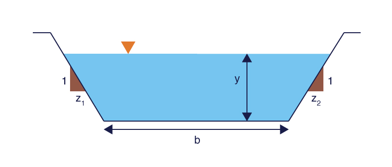
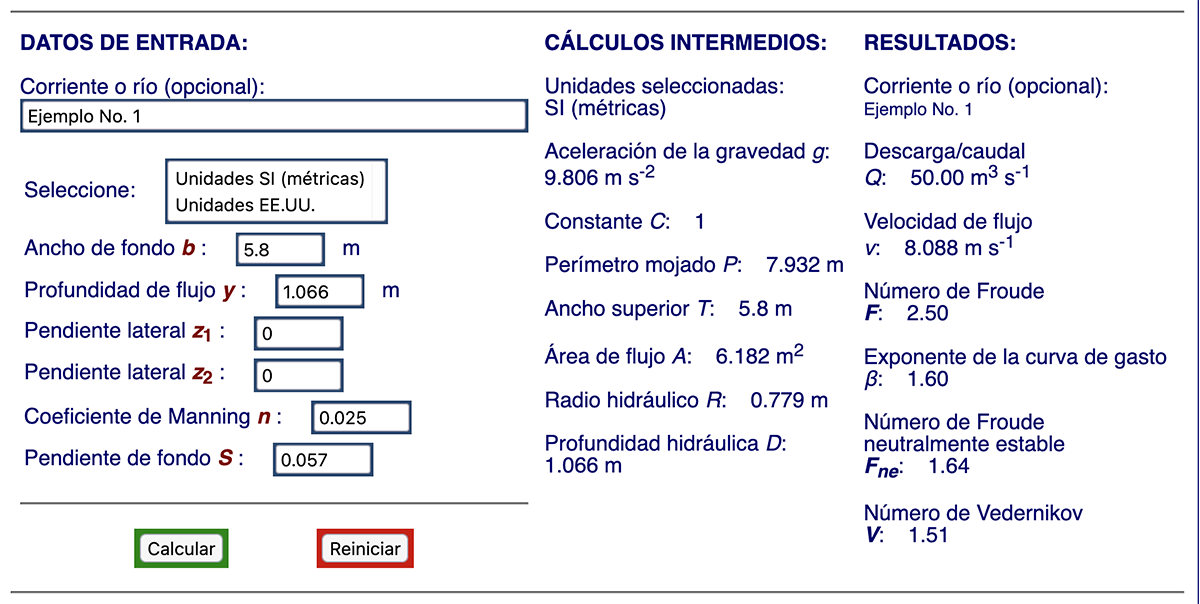
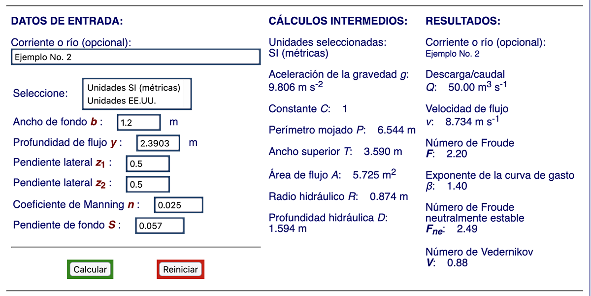
si el flujo puede volverse inestable o no. La calculadora canalenlinea15b calcula β para un canal prismático de sección transversal trapezoidal, rectangular o triangular (Fig. 10). Se requiere la siguiente entrada:
Para demostrar el funcionamiento de la calculadora en línea, se consideran dos ejemplos:
Los resultados son: Q = 50 m3/s; v = 8,088 m/s;
F = 2,50; β = 1,60; Fns = 1,64, y
V = 1,51.
En el Ejemplo No. 2, se asume: b = 1,2 m,
y = 2,3903 m,
z1 = 0,5,
z2 = 0,5,
n = 0,025, and
S = 0,057.
Los resultados son: Q = 50 m3/s;
v = 8,734 m/s;
F = 2,20;
β = 1,4;
Fns = 2,49, y
Cabe señalar que la elección de la forma de la sección transversal y las dimensiones del canal con el objetivo de reducir β debe hacerse muy cuidadosamente. Por ejemplo, un canal trapezoidal ancho no necesariamente conduce a una reducción del valor de β, porque el aumento del ancho superior T dará como resultado una disminución de la profundidad hidráulica D, lo que conducirá a un aumento de los números de Froude y Vedernikov. 9. LA NATURALEZA DE β
El valor de β es menor no sólo para canales triangulares,
sino también para canales estrechos.
La Tabla 3 lleva a las siguientes conclusiones:
Para los canales de prueba dados, la Tabla 3 muestra que a medida que β disminuye, V también disminuye. En particular, para los casos de prueba 2 a 6, el número de Vedernikov permanece V < 1, asegurando la estabilidad del flujo y la consiguiente ausencia de ondas de rollo. Además, para la sección muy estrecha (i = 6), β se reduce aún más, a β = 1,269, con un correspondiente V = 0,181, este último considerado un valor definitivamente bajo. Concluimos que el parámetro β es de suma importancia en el diseño hidráulico de canales para evitar la inestabilidad del flujo y las ondas de rollo asociadas con esta condición. 10. CONTROL MECÁNICO DE LAS ONDAS DE ROLLO El criterio de Vedernikov se considera una condición necesaria, pero puede ser no suficiente para la ocurrencia de ondas de rollo (véase la Sección 5). Dado que existe una escala preferencial de números de onda adimensionales para la propagación de ondas de rollo (Fig. 8), la ocurrencia de un evento de onda de rollo también puede depender de la condición de contorno aguas arriba, es decir, de la escala espacial (adimensional) de la onda entrante. Por lo tanto, existe una situación aleatoria en la ocurrencia de un evento de onda de rollo, lo cual impide que ocurra con demasiada frecuencia o, inclusive, a intervalos de tiempo regulares.
Además de la evaluación precisa del número de Vedernikov, las ondas de rollo también pueden controlarse
atenuando mecánicamente (es decir, difusionando) los números de onda preferenciales si estuvieran presentes en las vecindades de la entrada al canal revestido.
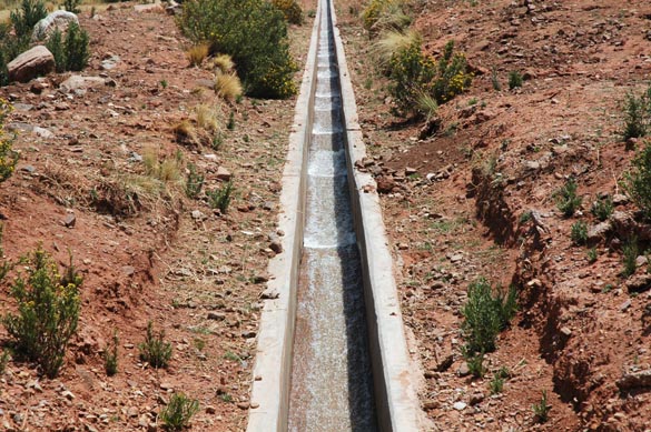
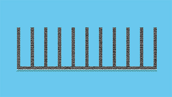
Esto puede lograrse colocando (construyendo) un difusor de momento, o impulso
(momentum diffuser) en el inicio del canal revestido, o muy próximo a él. Un difusor de momento separa
el flujo en una serie de canaletas estrechas
En la práctica, un difusor de momento correctamente diseñado probablemente requerirá una modelación física y/o matemática para determinar adecuadamente sus propiedades hidráulicas y dimensionar sus características geométricas. 11. ESTUDIO DE CASO: TRIBUTARIOS DEL RÍO LA PAZ, BOLIVIA
Los hallazgos de este artículo se complementan con un estudio de caso de dos afluentes del río La Paz,
que atraviesan la ciudad de Nuestra Señora de La Paz, comúnmente conocida simplemente como La Paz,
en el departamento del mismo nombre, Bolivia. El departamento de La Paz se muestra en color vino,
inmediatamente al este de Perú en el mapa de la derecha (Fig. 15). Nótese la ubicación aproximada
de la cuenca hidrográfica como el pequeño punto azul dentro del departamento.
La cuenca del río La Paz comprende 496,4 km2 y cuenta con seis (6) afluentes: (1) Choqueyapu,
Los canales se construyen utilizando muros de mampostería de piedra, con los lechos de canal sin revestimiento; consulte las Figuras 16 y 17. La mayoría de los tramos del canal tienen caídas verticales en el cauce para la reducción y control de la pendiente (Tabla 4). Se ha calculado un valor aproximado de celeridad de onda c = 10,5 m/s a partir de videos disponibles de eventos de ondas de rollo. Por lo tanto, asumiendo un valor de β ≈ 1.5, la velocidad media del flujo (ahora denominada v) puede aproximarse de la siguiente manera: v = c / β = 7 m/s.
A la espera de estudios más detallados, el coeficiente de fricción de Manning se ha estimado en
La Tabla 5 muestra los cálculos de β y V para siete (7) tramos de canal seleccionados
(estaciones) con pendientes locales relativamente pronunciadas (Slocal ≥ 0.034; Tabla 4).
Con el fin de comparar eventos de frecuencia similar, las profundidades de flujo se
establecieron para pasar el mismo caudal, elegido como
Se observa que todos los tramos del canal considerados tienen números de Vedernikov V > 1,
lo que confirma las condiciones hidráulicas en las que es probable que se produzcan ondas de
rollo. Además, se muestra que todos los tramos tienen β > 1.6, es decir, claramente
cerca del límite superior del rango factible La existencia de caídas en el canal añade un poco de complejidad al análisis, ya que el flujo ya no se puede considerar estrictamente unidimensional. Por lo tanto, el presente análisis es solo una aproximación, sujeta a una detallada verificación de campo en el momento apropiado.
12. CONCLUSIONES
Se examinan los fundamentos teóricos y la experiencia relacionada con la inestabilidad del flujo en canales abiertos con el objetivo de controlar
las ondas de rollo. Estas últimas parecen repetirse con relativa frecuencia en ríos canalizados en los cuales el número de Vedernikov ha aumentado,
debido a la canalización, por encima del umbral
Se demuestra que la elección de β (en la etapa de diseño) es de suma importancia en el
control de las ondas de rollo. Varios ejemplos
apuntan de manera concluyente a la existencia de una relación definida entre β y V, a saber, que a medida que la forma de la sección transversal
se aleja de rectangular, hacia trapezoidal y triangular, β disminuye correspondientemente, lo cual reduce el valor de V.
La teoría de propagación de ondas poco profundas revela la existencia de una escala espacial preferencial para la amplificación de perturbaciones
superficiales
La metodología presentada en este artículo se ha aplicado a dos ríos canalizados en La Paz, Bolivia, en los cuales se ha comprobado que las grandes
ondas de rollo (ondas pulsantes) recurren con una frecuencia bastante preocupante. El análisis confirma que donde se han producido ondas de rollo
en estos ríos canalizados, lo han hecho bajo REFERENCIAS
Brock, R. R. (1967). Development of roll waves in open channels. Report No. KH. R-16,
W. M. Keck Laboratory of Hydraulics and Water Resources, California institute of Technology, Pasadena. Calif.
Chow, V. T. 1959. Open-channel Hydraulics. Mc-Graw Hill, New York.
Cornish, V. 1907. Progressive waves in rivers. Journal of the Royal Geographical Society, Vol. 29, No. 1, January, 23-31.
Craya, A. 1945. Calcul graphique des régimes variables dans lex canaux. La Hoiulle Blanche, No. 1, 39-60.
Craya, A. 1952.
The criterion for the possibility of roll wave formation. Gravity Waves, Circular 521, 141-151,
National Institute of Standards and Technology, Gaithersburg, MD.
Lagrange, J. L. de. 1788. Mécanique analytique. Paris, part 2, section II, article 2, p 192.
Liggett, J. A. (1975). Stability, in Unsteady flow in open channels,
Vol. 1, K. Mahmood and V. Yevjevich, eds., Water Resources Publications, Fort Collins, Colo., 259-281.
Lighthill, M. J., y G. B. Whitham. 1955.
On kinematic waves: I. Flood movement in long rivers. Proceedings, Royal Society of London, Series A, 229, 281-316.
Plan Maestro de Drenaje. 2007. Revisión y Actualización del Plan Maestro de Drenaje para la Ciudad de La Paz. Informe Final,
Gobierno Municipal de La Paz (GMLP), República de Bolivia,
Octubre.
Ponce, V, M., y D. B. Simons. 1977. Shallow wave propagation in open-channel flow. Journal of the Hydraulics Division, ASCE, Vol. 103, No. HY12, December, 1461-1476.
Ponce, V, M., y D. Windingland. 1977. Kinematic shock: Sentitivity analysis. Journal of the Hydraulics Division, ASCE, Vol. 111,
No. HY4, April, 600-611..
Ponce, V. M. 1991. New perspective on the Vedernikov number. Water Resources Research, Vol. 27, No. 7, 1777-1779, July.
Ponce, V, M., y M. P. Maisner. 1993.
Verification of theory of roll wave formation. Journal of Hydraulic Engineering, ASCE, Vol. 119, No. 6, June, 768-773.
Ponce, V. M., y P. J. Porras. 1995. Effect of cross-sectional shape on free-surface instability. Journal of Hydraulic Engineering, ASCE, Vol. 121, No. 4, April,
376-380.
Ponce, V. M. 2002. That's the one we skip! Legacy Tale. ponce.sdsu.edu
Ponce, V. M. 2014. Fundamentals of open-channel hydraulics. Online textbook.
Ponce, V. M. 2014. Chow,
Froude and Vedernikov. Online paper.
Ponce, V. M. y M. Diaz. 2016. The inherently stable channel with online computation. Online paper.
Powell, R. W. 1948.
Vedernikov's criterion for ultra-rapid flow.
Transactions, American Geophysical Union, Vol. 29, No. 6, 882-886.
Seddon, J. A. 1900. River hydraulics.
Transactions, ASCE,
Vol. XLIII, 179-243, June.
Vedernikov, V. V. 1945. Conditions at the front of a translation wave disturbing a steady motion of a real fluid. Doklady Akademii Nauk USSR, 48(4), 239-242.
Vedernikov, V. V. 1946. Characteristic features of a liquid flow in an open channel. Doklady Akademmi Nauk USSR, 52(3), 207-210.
| |||||||||||||||||||||||||||||||||||||||||||||||||||||||||||||||||||||||||||||||||||||||||||||||||||||||||||||||||||||||||||||||||||||||||||||||||||||||||||||||||||||||||||||||||||||||||||||||||||||||||||||||||||||||||||||||||||||||||||||||||||||||||||||||||||||||||||||||||||||||||||||||||||||||||||||||||||||||||||||||||||||||||||||||||||||||||||||||||||||||||||||||||||||||||||||||||||||||||||||||||||||||||||||||||||||||||||||||||||||||||||||||||||||||||||||||||||||||||||||||||||||||||||||||||||||||||||||||||
| 241206 |
